Monday 22 October 2012

ARITHMETIC FOR COMPUTER AND DIGITAL LOGIC (Nurul Ain Farhana Binti Che Ab Manan)


ARITHMETIC FOR COMPUTER.

Number System Base .

WHAT IS A BASE FOR NUMBER SYSTEM TYPES ?
Most of the numbering system will have a base .


Ø  DECIMAL NUMBER:

*    Base of 10 .
*    The value of the assigned weight is composed by 10 digits starting from 0 until 9 .
*      The positive and negative values are determined by their position weight structure .


Ø  BINARY NUMBER:

*    Base of 10 .
*    The number consists of  0 and 1 digit only.
*     


*      The least significant bit (LSB) and most significant bits                     (MSB) is depends on the size of binary number. 


Ø  HEXADECIMAL NUMBER : 

           *     Base of 16 .
           *    The value of the assigned weight is composed by 16                                 digits starting from 0 until F .
           *    The number is suitable to present in fours bit number .


Ø  BINARY DIVISION

EXAMPLE 1 :

             1)     1010  /  111 = 


    EXAMPLE 2 :

              2)      110 / 10 =


   digital logic

Combinational Circuits
·  A logic block contains no memory and computes the output given the current inputs .
·       It can be defined by three ways:


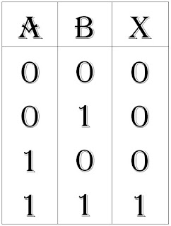
TRUTH TABLE 

Ø  Show many possible combinations of input values .
Ø  Between the input values and the result of a specific Boolean operator or combinations on the input variables .


EXAMPLE :
                    F = AB’ + A’B

GRAPHICAL SYMBOLS :

Ø Layout of connected gates that represent the logic circuit .

 F = AB’ + A’B

BOOLEAN EQUATIONS :

Ø Boolean function that consists possible combination of inputs that produce an output signal .


BOOLEAN EQUATION FORMS
*    Combinations of variables and operators . Typically , it has one or more inputs and produces an output in the range of 1 or 0 .
*      It can be represent in two forms :

 Sum-of-products (SOP)
 *  Combination of input values that produce 1 is convert into equivalent variables .
  *     SOP is easier to derive from truth table .
  *     TRUTH TABLE : F = AB’ + A’B

 SOP expression : F = (A’B) + (AB) + (A’B) + (AB)


Product-of-sums (POS)
 *   Input combinations that produce 0 in the sum terms and convert it into equivalent variables .
 *   Usually use if more 1 produce in output function .
 *   TRUTH TABLE : F = AB’ + A’B

POS expression : F = (A’B’) + (AB’) + (A’B’) + ( AB’)


                                   KARNAUGH  MAP ..

  • A grid-like representation of a truth table.
  • The rows and column correspond to the possible values of the    function’s input.
  • Each cell represents the output of the functions for those possible inputs.


        # n input  =  2n


 X = (A’D) + (B’D’) + (AB’CD).


Number System Conversion by Nurul Faizah

NUMBER SYSTEM CONVERSION


1. BINARY TO OCTAL

  • Bits from binary will be grouped into 3 bit starting from LSB.
  • Each 3 bits group will be converted to octal.
  • Example : 

2. OCTAL TO BINARY

  • Converting octal to binary, is usually by referring the conversion table as shown above.
  • Each octal number have their own binary number, grouped in 3 bits per number.
  • Example : 

3. HEXADECIMAL TO BINARY

  • Converting hexadecimal to binary, is usually by referring the conversion table as shown above.
  • Each octal number have their own binary number, grouped in 4 bits per number.
  • Example :

4. BINARY TO HEXADECIMAL

  • Bits from binary will be grouped into 4 bit.
  • Each 4 bits group will be converted to hexadecimal by referring to the table shown above.
  • Example :


by Nurul Faizah binti Sasaruddin - B031210257


Number Operation ; Subtraction by Nurul Faizah

1. How to subtract binary number


  • Align the two numbers as you would in decimal subtraction.
  • Work the columns right to left subtracting in each column. If you must subtract a one from a zero, you need to “borrow” from the left, just as in decimal subtraction.
  • One borrow represent 1, so, if 0 - 1 , = 2-1 = 1
  • Remember, 0 - 1 = 1 , 10 = 2.


2. How to subtract octal number


  • Align the two numbers as you would in decimal subtraction.
  • Work the columns right to left subtracting in each column. If you must subtract a one from a smaller number, you need to “borrow” from the left, just as in decimal subtraction.
  • One borrow represent 8.
  • Add the borrowed value to the smaller value.


3. How to subtract hexadecimal number


  • Align the two numbers as you would in decimal subtraction.
  • Work the columns right to left subtracting in each column. If you must subtract a one from a smaller number, you need to “borrow” from the left, just as in decimal subtraction.
  • One borrow represent 16.
  • Add the borrowed value to the smaller value.
  • Remember,
    • A = 10
    • B = 11
    • C = 12
    • D = 13
    • E = 14
    • F = 15


by : Nurul Faizah binti Sasaruddin - B031210257


Digital Logic - Universal Gates by Nurul Jamal

Universal gates are combination of any gates like AND,OR and NOT. NAND and NOR are such examples.
Figure 1 : Graphical symbols for NAND gate. Combination from NOT and AND gate.


Figure 2 : Truth table for NAND gate.


Figure 3 : Graphical symbols for NOR gate. Combination from NOT and OR gate.


Figure 4 : Truth table for NOR gate.

There are more universal gates and you can just search it in the search engines. Here are some exercise for you guys to try! :)
> ABC + (ABC)'
> A(BC' + A'B)
> (A+B)(A+C)(A'C)


Posted by,
Nurul Asyikin Binti Jamalulail (B031210038)


Truth Table by Nurul Faizah Sasaruddin


Boolean algebra uses variables and operators to represent logic circuit. The variables and function have only one value, 0 and 1, high and low. The complement of a variable is shown by a bar over the letter such as A with a straight line above it, or apostrophe A'.

AND gate represent multiplication operation of input value.

OR gate represent adding operation of input value.

NOT or inverter will inverting the input value.

NAND or NOT AND represent multiplication and inverting the input value.

NOR or NOT OR represent adding and inverting the input value.


A clip below shows you the graphical symbol and truth table for each gate.


1 + 1 = 0
1 + 0 = 1
1 x 1 = 1
1 x 0 = 0

The name of gates, graphical symbol, algebraic expressions and truth table for each gate as shown below.

1. AND


2. OR


3. NOT


4. NAND

also can be drawn as below


5. NOR

also can be drawn as below


posted by: Nurul Faizah binti Sasaruddin - B031210257